Like any hydraulic system, the most important part of the design is choosing the right components for the specific application and of course implementing them in the correct position in the circuit. As you can see above, The application of lifting up a robotic platform with the weigth of minimum one TON requires proper hydrostatic power generator and also hydraulic actuators. To reach this goal we need to find out first how much force we need to create to be able to lift up the platform.
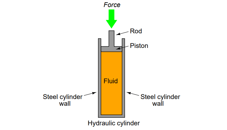
Using the Equation of F=PxA where F is force in N and A is the effective area m°2 inside the cylinder and P is the pressure of fluid in Pascal, We can calculate amound of required force and needed Pressure to obtain that force. The calculation lead us to the following model of cylinder with following specification:
Model Code: CDT3ME5
Bore Dia: 125 mm
Stroke: 500 mm
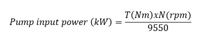
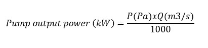
After Chosing the proper Cylinder and the required cylinder stroke its time to select the proper pump size. For this application there is no need of variable pump size since We do not have a rotary Actuator like a motor that need speed changing for example. Thefore the power unit can be chosen easier. Parker has a very compact and effective power unit in its product categories. If you consider the pump input power and output power equations as below:
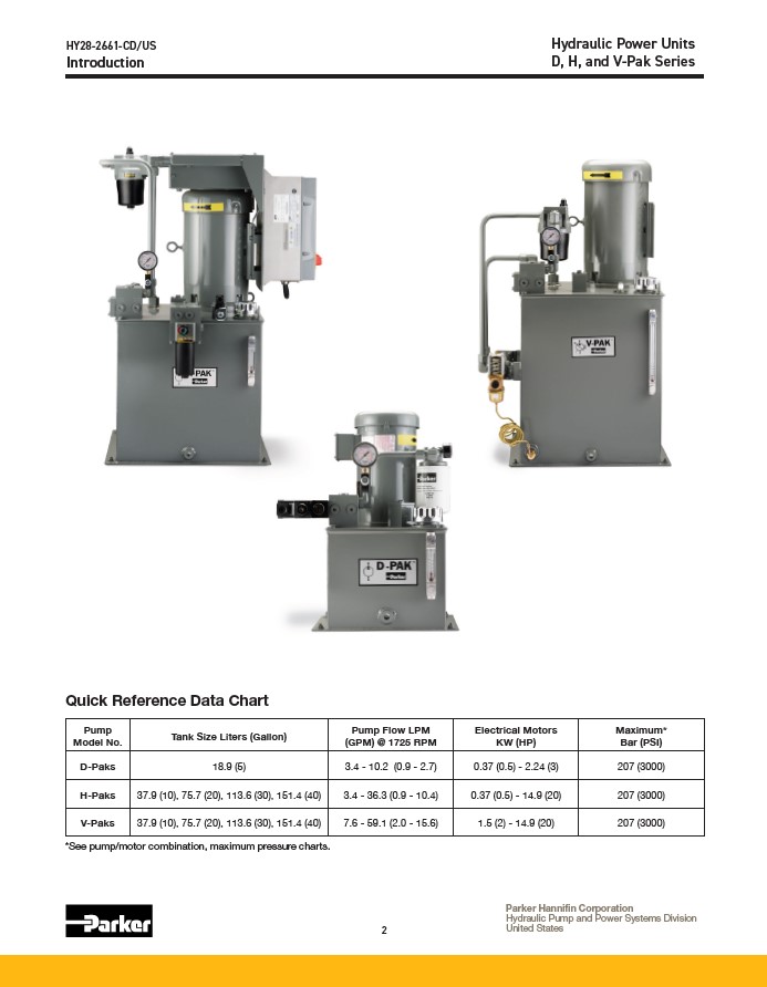
The calculated pressure is Max 200 Bar, The flow rate is about 20 L/Min therfore The vpak from Parker is an ideal choice,
The other Items existing in the hydraulic system are important and are chosen accordingly:
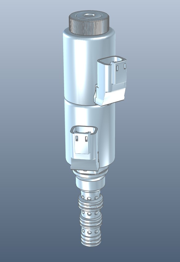
1- Directional Valve Block
The directional valve block is made of an spool inside a cylinder that is mechanically or electrically actuated. the position of the spool defines the path and direction of the fluid inside the hydraulic circuit.
the Model of the valve considering the chosen flow rate is Solenoid operated valves direct acting spool 4-way 3-position with an ID: OD146078KK2100
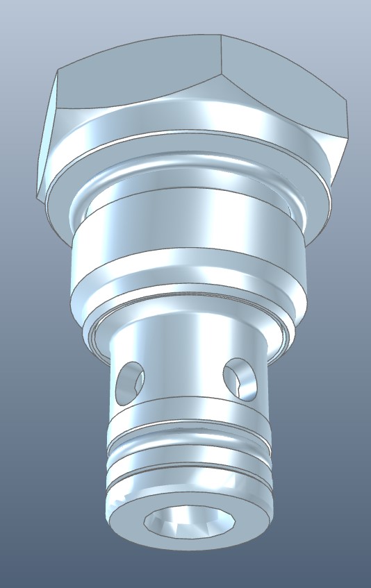
2- Check valve
This type of the valve is used to be sure that there is no flow back to the pump if there is path shift managed by the directional valve. Its important to keep the back flow away from the power unit. The ID of the Check valve of our system is: 043120005605000
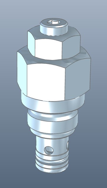
3- Relief Valve
The idea of using a relief Valve is to release the excessive fluid pressure inside the Cicuit caused by stalking of pump, actuator or motor. Its an vital component of every hdrostatic power transmission system. The relief pressure for our system is set to be 105 bar and the model ID is: 041156038505000
4- Needle Restrictor, free reverse Flow Valve
With flow from 2 to 1, the valve provides a fully adjustable orifice restriction. Free flow is permitted from 1 to 2, regardless of valve adjustment, by when pressure overcomes the spring bias of the valve’s check function. The model ID :040103035600000
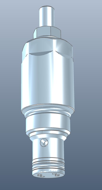
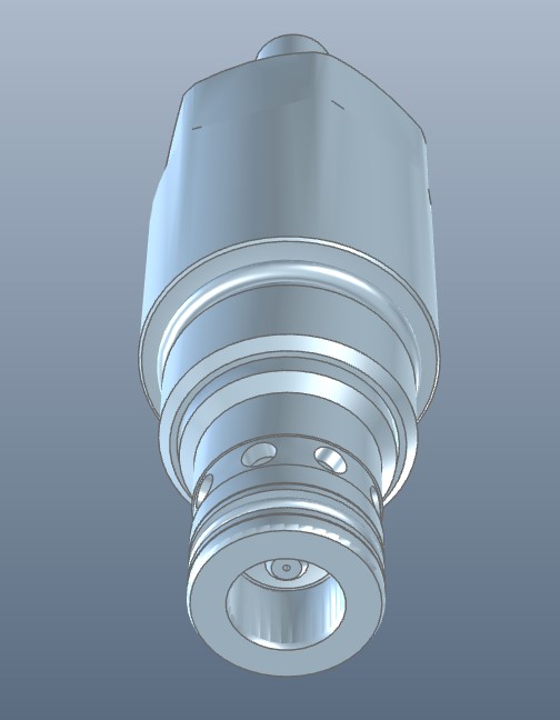
5- Relief pilot operated poppet type
Flow is blocked from 1 to 2 until pressure increases to meet the selected valve setting, lifting the conical, pilot-stage poppet from its seat. This action exhausts oil above the main-stage poppet (lowleakage, seat type), allowing it to shift and provide relief flow through 2 to tank. Pressure at 2 is additive to the relief setting of the valve. The ID model is 04120903851000A

Donnation!
Please help me to keep creating content on this blog. Thanks 🙂
€5.00


Leave a comment